SolidCNC CAD-CAM System
SolidCNC has a geometry kernel that had been developped by company it self and
there is not an external dependency.
SolidCNC can import IGES , DXF , VRML and STL files from other CAD-CAM
systems and make its own geometry objects , render them by open GL.
There are basic modelling functionality that lets users to make lines , arcs , curves ,
surfaces and primitive solid bodies from scratch. Users can use many
interactive functions that SolidCNC apply on the geometry entities.
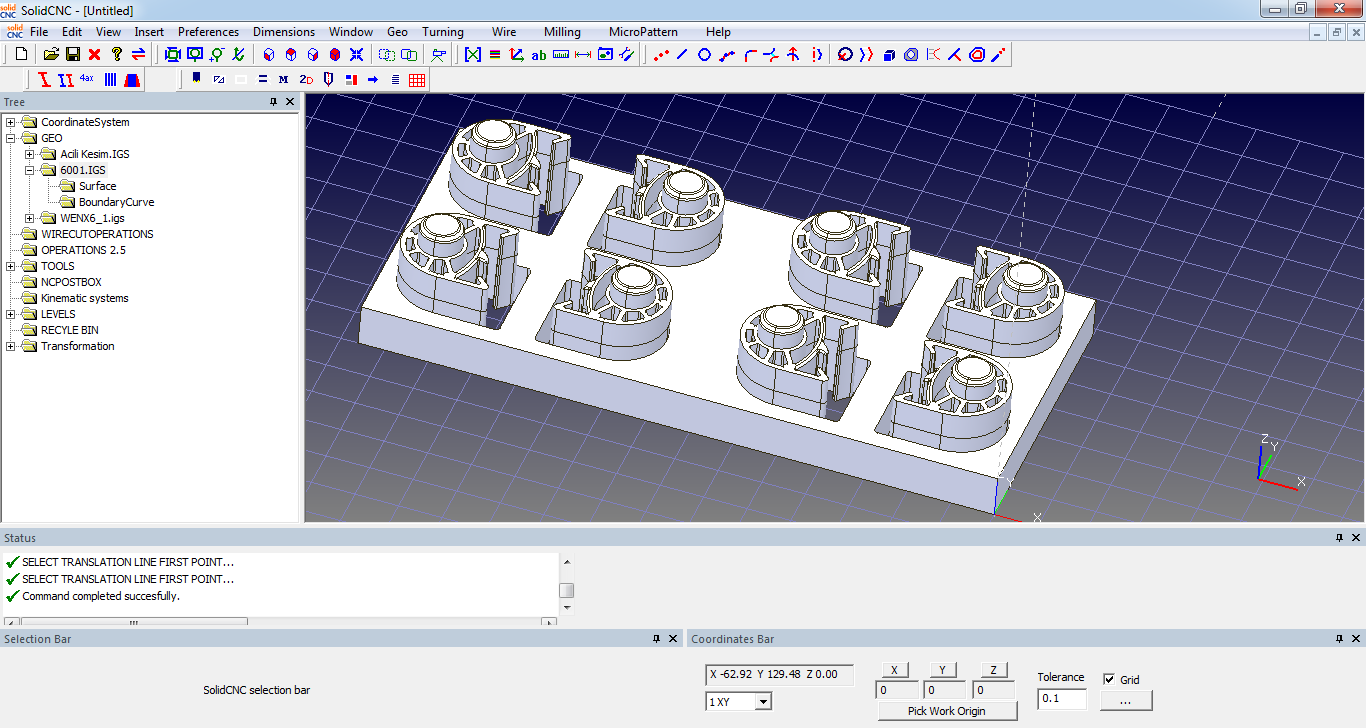
Courtesy of Kayapen – Sinop , A mold model which was exported from SolidWorks CAD system
Modelling fuctions of SolidCNC
You can make lines , circles , arcs ,ellipses and cubic splines from scratch. You may trim the curves where they intersect , make ofset curves , project them on other planes or surfaces. There are some simple surface modelling functionality as extruding curves to make tabulated cylinders , or revolve curves and make surface of revolution , or make ruled surface between curve sets. Trimming surfaces or closing the holes on trimmed surfaces is possible. Sectioning the surfaces by planes is also possible. SolidCNC is capable of many geometric functions on curve and surface entities.
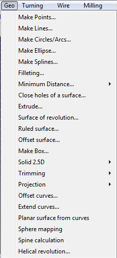
You can attach texture to surface entities on SolidCNC by selecting image files. It is possible to import VRML files to get texture map models from other software systems.
Courtesy of Karel Kalıp , Istanbul 2013 Texture map models imported to SolidCNC by VRML file
It is possible to change the positions of geometric entities which are imported or modelled on SolidCNC by transformation functions. Rotations , linear moving , mirroring , scaling can be applied.
Digitised models (STL files) can be opened
Courtesy of Dokuz Eylül University Izmir 2011 – prothesis model

Triangle mesh models may also be transformed or curve models may be formed by sectioning triangle meshes.
Courtesy of Polo sehpa – İnegöl 2014 a digitised hand made wood work
Click here to review the Compact Modular Cutting